A more advanced routing architecture for AWS VPCs.
TLDR: TGW can route traffic based on the source VPC as well as the destination IP.
Before AWS introduced Transit Gateway, the only way to connect VPCs together was to use VPC peering. The main issue with this approach is that you need a VPC Peering between each pair of VPCs that you want to connect.
To simplify large multi-VPC environments AWS released Transit Gateway, this allows for a hub-and-spoke model which allows for multiple VPCs to talk to each other with only a connection to a single hub.
The basic hub-and-spoke model would allow all VPCs to talk to all other VPCs (via routing, we are disregarding NACLs, SGs, etc.). In this case, all VPCs are associated with the same TGW Route Table.
A more advanced model is to have multiple TGW Route Tables attached to the same TGW. Doing so allows for different VPCs to talk to a different set of VPCs based solely on which TGW Route Table the source VPC is associated with.
The term for this is ‘multiple routing domains’ (although that term comes from a more complex networking concept).
To dive a little deeper:
- When you attach a VPC to the TGW you are creating a connection that allows for traffic to flow between the VPC and the TGW
- A TGW can have multiple TGW Routing Tables
- When you associate a VPC attachment to the TGW Route Table, you are telling the TGW which set of routing rules to use when traffic comes in from that VPC
- The routing rules of the TGW Routing Table allows for the traffic to be directed to any of the attached VPCs, not just those that are associated with the same TGW Routing Table
- When you create a propagation you are telling the TGW to automatically create a route in that TGW Route Table that has the propagated VPCs CIDR ranges point to that VPCs attachment
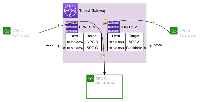
Let’s take a look at an example in diagram form

- Traffic comes into the TGW from VPC A and is going to 10.3.0.1
- VPC A is associated with TGW RT 1, thus the TGW will use that set of routing rules
- TGW RT 1 says that traffic should go to VPC C
- Traffic comes in from VPC B going to 10.3.0.1
- VPC B is associated with TGW RT 2
- TGW RT 2 says that traffic should be blackholed
This is a simple example but we can extend the concept to allow for various architectures.
For example:
- Workload VPCs might all be able to talk to a Shared Services VPC but not to each other (being controlled on the routing level, as opposed to NACLs or SGs)
- Traffic going out to the internet might be routed through the TGW and directed to a security VPC and through a firewall at which point it would go to a VPC with internet access. Thus only the security VPC can access the internet directly and the routing rules direct all outbound traffic from other VPCs to the firewalls instead.
- Dev and Test VPCs use resources in the cloud whereas production is instead directed to resources OnPrem